The Circuit Board biome in Defense of Kyrath was built like this: a single carefully-written prompt to a Claude Code agent, then three hours of waiting.
In that window the agent ran autonomously against the TiGen procedural-generation pipeline and its bootstrap skills. It spawned sub-agents for individual sub-tasks — per-component sprite authoring, palette tuning, motif composition, basemap generation, validation — and integrated their work back into the registries. At the end of the run there were eleven new sprite generators, three new interior generators, a new biome registry entry, motif compositions, a small cross-cutting feature added to the path system, and four sample basemaps that rendered cleanly through the same export pipeline every other biome uses.
That sounds like a stunt. It isn’t, quite. It’s what falls out of a procedural-generation pipeline that was already designed to receive that kind of work — every gameplay value living in data, every generator extending a documented base class, every biome reduced to a registry entry, and a chain of bootstrap skills that encode the procedural-content rules. None of that scaffolding was new. The agent just operated against it.
The output: a circuit board.
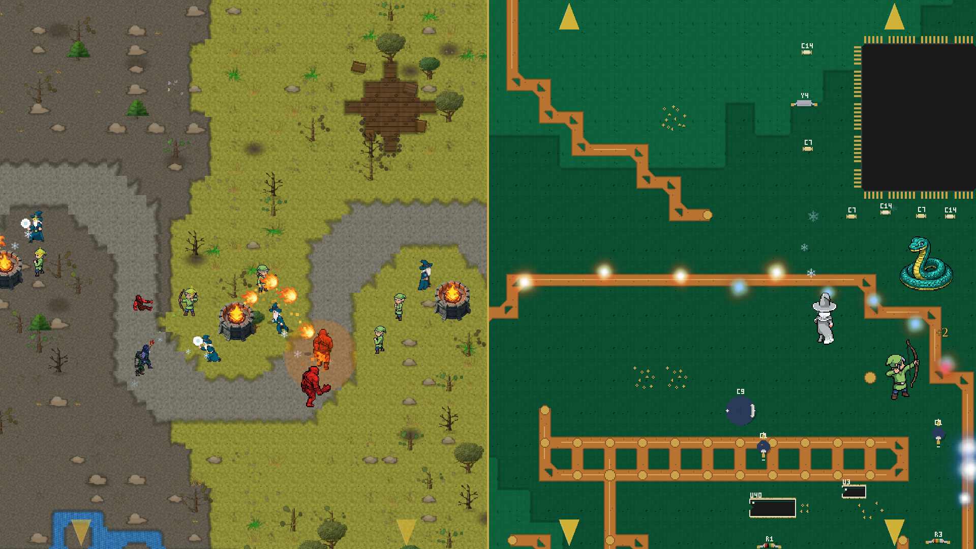
LevelModel, same path generators, same six-stage build. The two halves of this image are the same code path with different registry entries.Copper traces are the paths. Solder pads and silicon chips are the terrain. Wardens — the same medieval-styled wardens that defend deep forests and volcanic badlands elsewhere in the campaign — defend a motherboard. Four levels of this ship at launch.
This article is for readers who want the engineering view of what made the autonomous run possible: what survived the move from fantasy to silicon, what had to be added, and the cross-cutting feature that fell out of building it. The orchestration story comes back at the end with a few more details.
What survived the move
A Defense of Kyrath level is the output of a six-stage pipeline:
build_terrain → build_river → build_path → build_formations → build_decorations → build_motifs
Every biome in the game runs through these stages in the same order. Forests, meadows, dustbowl steppes, volcanic badlands, and now PCB. Each stage reads the same LevelModel dataclass and writes into the same shared collision layer (blocked_cells), so downstream stages can place props without colliding with rivers, paths, or formations placed earlier. The motherboard isn’t a special case — it’s a registry entry.
The path generators are the biggest survivor. Zigzag, switchback, arc, split, parallel lanes, converging tributaries, dual independent paths — the full single-path and multi-path roster from the paths and rivers article — work on PCB layouts unchanged. A zigzag through the steppes is a dirt road that winds back and forth across a dustbowl. A zigzag through a PCB is a copper trace that winds back and forth between chips. Bresenham still rasterizes the straight segments. Quadratic Bézier curves still smooth the corners. Chebyshev dilation still thickens the centerline into a walkable lane.
The layer system survived too. Terrain, river, path, ground detail, obstacles, props — same z-ordering, same physics conventions, same y-sort rules. Every PCB component sits at the obstacle or prop layer, which means tower placement and pathfinding logic are identical to the forest case. A warden placed near a QFP chip behaves the same way as a warden placed near a boulder — both are obstacles with circle collision in the same coordinate system.
The data-driven design pays compound interest here. Because every gameplay value lives in data, not code, a “biome” is a registry entry pointing at tile generators, sprite generators, decoration sheets, and motifs. PCB is one more entry in biome_registry.json alongside pastoral, deep_forest, steppes, and volcanic_badlands. Validation, level export, the in-game tile loader — none of it knows the new biome is special.
The shared base class — and why it mirrors the trees
The pipeline was happy to render silicon. The generators that produce the content on top of it had to be written.
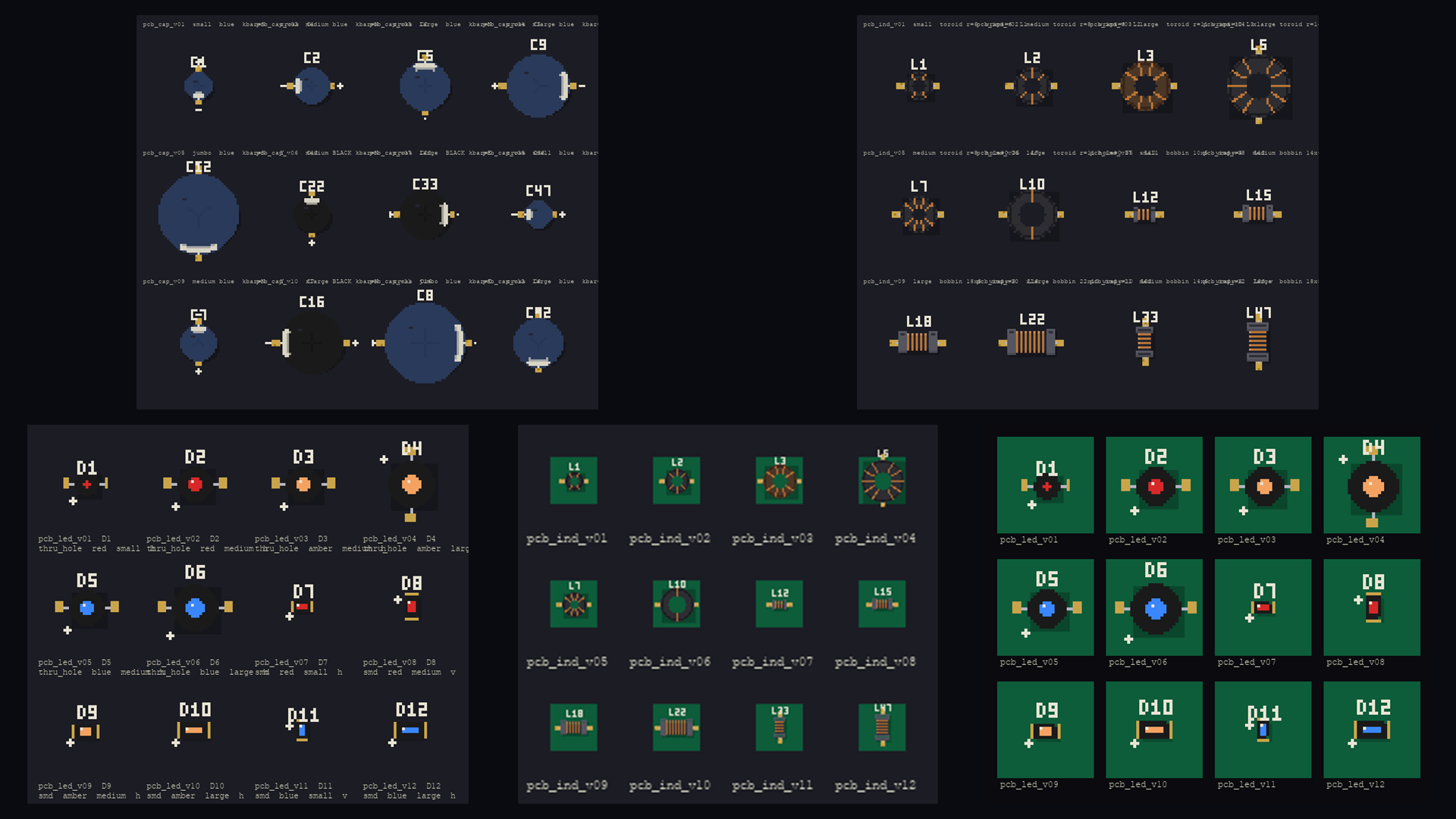
Eleven new sprite generators ship for the Circuit Board biome: DIP chips, QFP chips, electrolytic and ceramic capacitors, inductors, crystals, LEDs, heat sinks, connectors, resistors, and a shared abstract base class — BaseElectronicComponent — that handles the package geometry shared across all of them. Three new interior generators ship for the things that live on the green substrate without being components in their own right: silkscreen designators (R12, U7, C44 — those tiny white reference labels next to every part on a real board), fiducial alignment marks, and via clusters.
The base class architecture is deliberately the same architecture used by the medieval biomes’ tree generators. BaseTreeGenerator is the abstract base for Conifer, Broadleaf, SparseCanopy, DeadTree. It owns shared trunk geometry, canopy lighting, and shadow rendering. Subclasses inherit those primitives and override the species-specific bits.
BaseElectronicComponent is the same idea, retargeted at silicon. It exposes nine pixel-precise rendering helpers — and every PCB sprite generator composes its image from some subset of them:
_draw_plastic_body_rect— matte plastic rectangle (DIP body, capacitor flank, connector shell). Solid fill, 1-px sheen line near the top, 1-px darker bottom edge for the shadow side. Deliberately not glossy — real PCB plastic is matte and the sheen is subtle._draw_plastic_body_round— matte plastic circle (cap top, LED dome, crystal can). Tiny upper-left highlight stamps the reflection that domed cylinders show under top-down lighting._draw_silkscreen_outline— thin 1-px rectangle drawn 1 pixel outside the body bbox, framing the component the way a real silkscreen does on a real board._draw_silkscreen_designator— renders strings likeU3,C12,R7in a hand-coded 3×5 pixel bitmap font. The glyph table is a dictionary inside the base class; each character is five rows of three-bit strings ("###","#.#"). Roughly 24 glyphs at the moment — enough for any designator a real board carries._draw_pad_rect— gold rectangle pad for SMD leads._draw_pad_dot— gold circle pad for through-hole leads._draw_pin1_indicator— small white dot marking pin 1 on a chip (real boards either dot the pin-1 corner or chamfer the silkscreen — both conventions are supported)._draw_height_shadow— a soft drop shadow stamped before the body so the body covers most of it; only the offset spill survives, suggesting the chip stands a millimetre or two above the board._draw_lead_dots— evenly-spaced through-hole pads along one edge, with acount == 1 → centreshortcut.
Every PCB sprite is composed from these helpers. No subclass reimplements a body or a pad or a designator — they orchestrate the primitives and supply geometry.
A pipeline walkthrough — the DIP chip
The cleanest example is the DIP (Dual In-line Package) chip generator. Pin counts 8/14/16/20/28/40 are all supported via a PIN_TABLE dict that maps each pin count to a (body_w, body_h, pads_per_side) triple. Two orientations are available — long axis east-west or north-south — so the same generator populates both axes of a board layout without any post-render rotation.
The 8-step generate(seed) pipeline:
- Drop shadow. Stamp a soft 1×1 offset shadow under the body bbox at alpha 70 — done first so subsequent layers sit on top.
- Lead pads. Place gold rectangles along the two long edges, centred under the body bbox. Pads protrude two pixels outside the body; the rest will be covered by the body fill.
- Plastic body. Solid matte-black rectangle on top of the inner pad ends, with the 1-px sheen line and bottom-edge shadow.
- Carve the pin-1 notch. Real DIPs have a semicircle notch on the pin-1 short edge. We carve it by walking a circle of radius 2 px and zeroing alpha for any pixel inside the body bbox — leaves the pad pixels untouched even where the carve passes near them.
- Silkscreen outline with notch gap. A 1-px rectangle one pixel outside the body, but with a small gap on the side of the body’s pin-1 notch — so the silkscreen mirrors the body cue.
- Pin-1 indicator dot. A 2×2 white block in the body’s pin-1 interior corner.
- Designator text.
U1,U13,U37rendered in the 3×5 font, positioned just outside the silkscreen on the appropriate side for the orientation. - Pad oxidation. A seeded
random.Randomstampsoxidation_countdarker pixels into each pad rectangle — but only if the underlying pixel is still the gold pad colour. This guarantees the tarnish never bleeds onto the body or the bare substrate, regardless of pad position. Setoxidation_count = 0for pristine boards; set it to 3 for the look of a board pulled out of a basement.
The QFP chip generator extends the same base, swaps in _pad_positions that lay leads on all four sides, supports two pin-1 conventions (dot for the same interior dot the DIP uses, or corner_bevel for a 45-degree silkscreen chamfer that scales with body size), and ships in pin counts 16/24/32/40/48/64. Roughly 80% of its rendering is inherited; the remaining 20% is QFP-specific geometry and the chamfer logic.
The electrolytic cap, ceramic cap, crystal, LED, and resistor generators each run the same kind of pipeline against a slightly different shape. Inductors and connectors get the most variation because their real-world appearance does. Every one of them ends up as a small, focused class — the longest is the DIP at ~400 lines including all the param specs and pixel-precise helpers.
The locked palette
Five colors do all the work. They live as class constants on BaseElectronicComponent and every sprite reads from the same source:
- Silkscreen off-white:
#e8e4d4 - Gold pad:
#c9a44a - IC plastic black:
#1a1a1a - IC plastic highlight (sheen):
#2a2a2a - Drop shadow: pure black at alpha 70
The gold-pad value #c9a44a is one channel away from Frosty Wren’s brand primary gold #c9a84c. That wasn’t planned, exactly — the PCB palette was tuned against reference photographs of real motherboards under top-down lighting — but the alignment is welcome. Wardens defending a motherboard happen to be defending it in the studio’s brand palette.
Authenticity — five rules from staring at real boards
A first pass that simply scattered electronic-themed sprites on a green field looked wrong — like a stock-photo collage, not a populated motherboard. Five rules came out of staring at reference photographs of real PCBs, and the codebase has a dedicated guide that ships with the repo enforcing them on any future PCB-targeted edit:
- Hierarchy, not uniformity. Real boards have one to three large dominant chips; everything else is supporting cast. A scatter of equally-sized DIP chips reads as fake. The PCB biome registry leans on motifs with a single QFP at 5×5 tiles or DIP at 4×2 tiles as the focal points; smaller components cluster around them.
- Components cluster around chips, not on the open board. Decoupling capacitors sit in tight rows along the power-pin edge of an IC. Random caps drifting on bare green substrate read as wrong. The motif system carries a
pcb_dip_socketmotif (chip + 4 caps + 2 resistors) that places those companions together by geometric anchor, not by independent scatter. - Vias form grids, not random scatter. A 3×3 grid of vias under a chip’s exposed pad is a thermal pattern; nine vias scattered across the same area is noise. The
pcb_viasdecoration sheet has four pre-arranged patterns — random, grid, row, ring — and grid/row/ring dominate the placement near chips. - Many decorative trace lines, not just the gameplay path. Real boards are criss-crossed with traces — typically dozens per square inch. The gameplay path should be one prominent trace among many. Rules 1, 2, 3, and 5 mostly fell out of the existing motif system. Rule 4 didn’t have a home.
- Silkscreen designators ride on components, not in open space. Floating “R12” labels in the middle of bare green look like decoration spam. The 3×5 font is the same one the chip generators use; the interior
PCBDesignatorgenerator scatters extras at low density (target ≤ 0.02) so test points and via labels appear without overwhelming the open zones.
The feature that came out of it
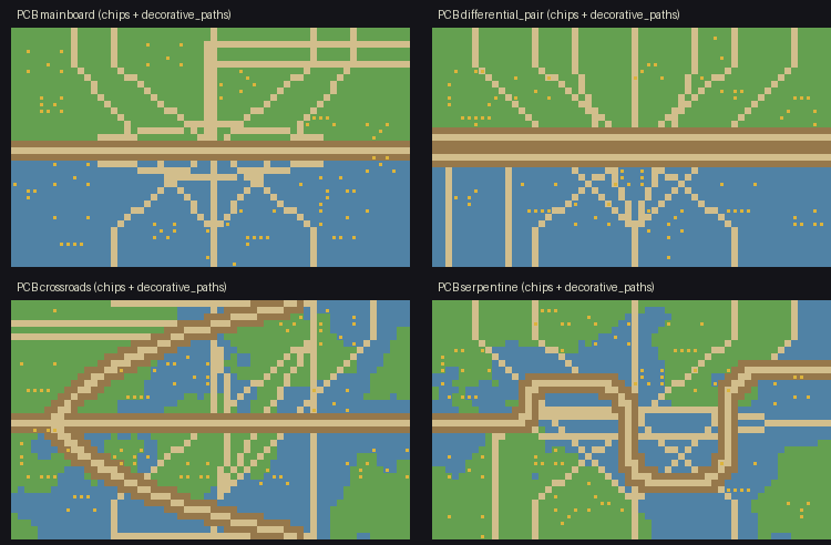
The fix for rule 4 is now a generic capability called decorative paths, living in path_gen.build_path().
A decorative path is a path-shape spec — same vocabulary as the gameplay path: zigzag, arc, switchback, diagonal, split — that contributes cells to the level’s path_cells (and therefore renders with the path tileset’s auto-tiling) but does not produce enemy waypoints. model.paths is unchanged. The wave system never sees them. The renderer does.
"path": {
  "paths": [{"start": "w", "end": "e", "shape": "zigzag", "winding": 3}],
  "decorative_paths": [
    {"start": "n", "end": "s", "shape": "arc", "bow_amount": 0.4},
    {"start": "n", "end": "e", "shape": "diagonal"},
    "...10 more..."
  ]
}
Decorative paths respect blocked_cells, so they route around chips and obstacles without manual tuning. Where they touch the gameplay path, the bitmask logic naturally forms gold-pad junctions — exactly the visual a real PCB shows where one trace meets another. The whole feature is fewer than 80 lines of dispatch in path_gen.py plus the same shape vocabulary that already existed.
It’s biome-agnostic. Any future biome that wants visual density beyond the gameplay path — irrigation channels in a farm biome, ley lines in an enchanted forest, cracks in a frozen lake — can use it without touching the path code again. PCB asked for it; the engine got it.
The biome as a configuration vector
Here’s the takeaway, as much as there is one.
Once a procedural pipeline is genuinely data-driven — generators in a registry, biomes as configuration, layers and collision unified, the renderer reading from a single source of truth — the cost of a new visual register is mostly the cost of new sprite generators and a registry entry. The engine doesn’t need to learn what a motherboard is. It just renders whatever the registry tells it to render in whatever palette the biome specifies.
That’s the boring part of the story. The interesting part is what falls out: authenticity work that’s specific to a single biome (the five PCB rules) sometimes produces capabilities that aren’t biome-specific at all (decorative paths). Build for one weird case carefully, and the engine gets a little more general every time.
Four PCB levels ship at launch. The pipeline that builds them is the same one that builds the forests, and a corner of the realm that no fantasy bestiary has ever charted is the proof.
Back to the orchestration
The intro promised a few more details on how the autonomous run actually went.
The prompt looked like a project brief — visual identity, the components that should exist, references to study, the authenticity rules to follow, what counted as done. The agent took that and ran. What’s worth describing isn’t the act of an agent producing code; it’s the shape of what an agent could actually accomplish here, given the scaffolding underneath:
- It read the registries, understood the conventions, and matched them. New sprite generators were authored to extend
BaseElectronicComponentbecause the base class existed and was documented. New tile entries followed the existingtile_registry.jsonschema because that schema was the contract. - It dispatched parallel work to sub-agents. One sub-agent worked on a single sprite generator end-to-end — param specs, geometry helpers, the eight-step
generate(seed)pipeline — while another tuned the palette and another composed motifs. The parent reviewed each sub-agent’s output, integrated it, and moved on. - It iterated against rendered output. When a generator emitted something that didn’t match a reference photograph or violated one of the authenticity rules, the agent edited the generator and re-rendered. Visual feedback loops, run autonomously.
- It hit walls and worked around them. The decorative-paths feature exists because the agent recognised that one gameplay path on bare green substrate didn’t satisfy the “many traces per square inch” rule, and the cleanest way to satisfy it was a generic path-system extension rather than a PCB-specific hack.
Three hours of that. The author started the run, came back to a working biome.
What this surfaces, more than the biome itself, is how much the leverage of an autonomous run depends on what’s underneath it. A procedural-generation pipeline whose generators are scattered across hardcoded constants, whose biomes are bespoke pipelines, whose rules live in habit rather than documentation — that pipeline doesn’t yield to a three-hour autonomous run. The rules need somewhere to live; the conventions need to be readable; the outputs need to be inspectable. Once that’s true, the surface area an agent has to reason about becomes small enough that a single prompt can drive a multi-hour build.
The medieval biomes in this game were built the way most game art is built — bespoke, hand-tuned, iterated with a human in every loop. They’re also what made the procedural scaffolding mature enough that the next biome could be built without one. Same pipeline, same registries, same authenticity discipline — different driver in the seat for the bootstrap.